There are a variety of factors that can hinder the accuracy of conductivity measurements in industrial applications — and not all of them stem from the process environment itself. Some first steps to ensuring accuracy would be taking a conductivity sensor’s measurement range and construction into account to avoid any issues. Proper installation is also a key factor in sensor accuracy. Operators should take care to consider these factors in order to avoid a phenomenon known as polarization.
What is Polarization?
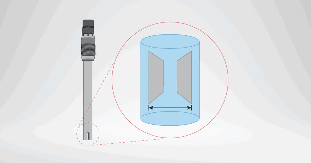
Polarization occurs when an electrical field builds up around the conductivity sensor’s electrodes. Essentially, the electrodes can become ovencumbered. The electrodes are responsible for interpreting the current caused by the ionic activity of a process, thus registering a conductivity measurement. As excessive ionic activity gathers around the electrodes, they form layers called electrical double layers. This buildup of ions near the electrodes changes the local concentration of ions. The ion layers act as barriers to current flow, reducing the effective area through which the current can pass. This can be seen with a 2-electrode sensor where impedance increases the resistance at the electrodes. This affects the overall conductivity measurement, i.e., polarization.
2-Electrode Sensors
The occurence of this phenomenon does not at all mean 2-electrode sensors are inept. The fact that polarization can occur with a 2-electrode sensor implies a process simply requires a sensor with more tools to combat the high ionic activity. Not all 2-electrode sensors will experience polarization. A 2-electrode sensor is perfectly suitable for most applications reading in microsiemens (µ/cm) and up to around 20 millisiemens (mS/cm). These sensors work excellent in applications with low, precise conductivity values. For processes with conductivity values that consistently read beyond these figures, 2-electrode sensors may become susceptible to polarization. The solution to these issues would be to consider a 4-electrode or toroidal conductivity sensor.
4-Electrode & Toroidal Sensors
4-electrode and toroidal conductivity sensors are typically better suited for processes with higher conductivity values. A primary benefit of 4-electrode sensors are the separate pairs of electrodes for applying current and measuring voltage. This helps to reduce the impact of polarization by separating the current-carrying and sensing functions.
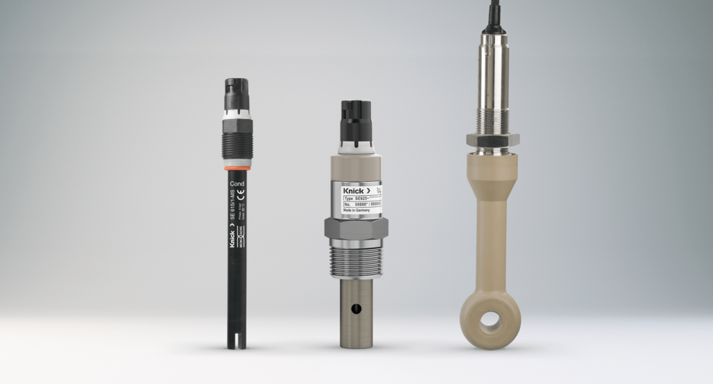
Toroidal conductivity sensors utilize coils or toroids to obtain conductivity values instead of contacting electrodes. A strong plastic housing often encases the coils of the measuring element. In processes with large ranges or where the media is corrosive or otherwise aggressive, toroidal conductivity sensors are a common choice for operators. The flexibility of the plastic used retains excellent mechanical and chemically resistant properties under high temperatures. These factors help to effectively eliminate cause for polarization.
Choosing the Right Conductivity Sensor
Conductivity sensors can vary dramatically in shape, size, and material of construction depending on the application. It is crucial to understand how you plan to use the sensor in your process so that you can select the right conducitvity sensor. Considering these factors will assist operators in mitigating polarization while keeping conductivity measurements consistent and accurate.